LED Displays & Electronic Message Centers
Hardware Support
Congratulations on owning a Stewart LED sign!
We want to make the process of operating, maintaining and servicing your LED sign as easy as possible. Here you can find instructions on replacing LED display components, installing and troubleshooting communication methods, and more.
Please see our Software Support page.
Operation
For general instructions on operating your LED sign hardware, including how to open the LED cabinet and vandal cover.
How the LED cabinet is opened depends on the sign model and build. For most DayStar signs and all TekStar signs, select from the tabs below. "Modular" DayStar signs and VividStar signs do not have opening sign cabinets; they are serviced through the removal of removal of dual maintenance LED modules.
- Disconnect power from the sign at the circuit breakers or other electrical switch.
- Remove the 9/16th inch fasteners from the bottom of the sign. The number of fasteners on the bottom of the sign will vary depending on the size of your sign.
- Use caution when opening the sign once the fasteners are removed. Stabilize the face of the sign with both hands, as it will open itself under the force of attached gas struts. The struts will safely hold the face open while servicing.
- Disconnect power from the sign at the circuit breakers or other electrical switch.
- There are three hex head screws along the bottom of each side of the sign. You will need a 5/16th inch nut driver to remove the screws and loosen the sign face.
- The sign is hinged at the top and will swing freely towards you. Hold the sign open using the supplied support rods. This will provide access to the inside of the sign and provide access to the fluorescent bulbs, ballast, ventilation fans and LED cabinet.
- To open the LED cabinet, unlatch the two buckles at the top of the cabinet. Once released, the face will swing down and provide access to the sign's internal components.
Some models of DayStar LED signs include a vandal cover over the LED display. Use the following instructions to access the front of the LED modules, or to install a vandal cover after the sign has been installed.
Opening
- Remove the three 5/16th inch self tapping screws from the bottom of the vandal cover face.
- Open the face and set both of the prop rods on either side into the prop rod holders.
Installation
- Remove the screws in the bottom of the frame.
- Remove the double-sided backing and position the frame around the LED panel.
- Use the 11 self-tapping screws, provided, to secure the frame to the cabinet
- Replace screws in the bottom of the frame when finished.
- Apply a bead of silicone adhesive caulk to the upper frame of the Defender Cover where it comes into contact with the upper cabinet.
Communication
How your LED sign transmits data to and from the controlling software is called the communication method. This option is selected at the time of sign purchase. Select your communication method below for setup and troubleshooting instructions.
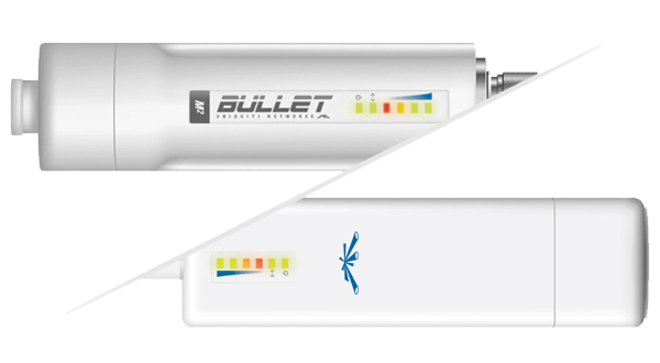
Short Range Wireless
Using Wi-Fi radios.
For direct line-of-sight communication over a maximum distance of 1500 feet.
Short Range Wireless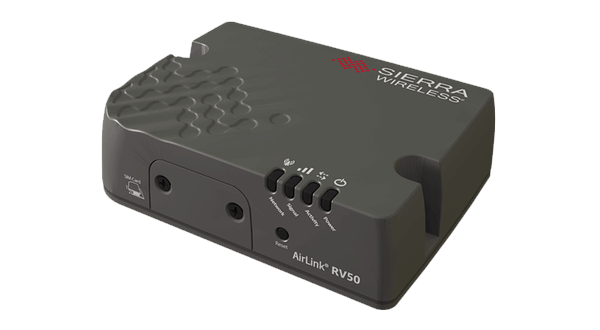
Long Range Wireless
Using a cellular modem.
For cellular communication using a customer-provided or Stewart-provided data plan.
Long Range Wireless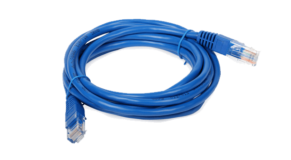
Wired Methods
Using an Ethernet or fiber optic cable.
For trenched communication cables, with our without signal boosting devices.
Wired MethodsPreventative Maintenance
Our signs have been designed and manufactured to provide years of trouble-free operation. This section describes some preventative maintenance steps that may be needed from time to time. We recommend following these steps every three months to ensure that your equipment is in good working order.
![]() Sign Maintenance Manual
for printable instructions.
Sign Maintenance Manual
for printable instructions.
It's critical to keep water from entering the LED display cabinet. Check the cabinet for signs of leakage, paying particular attention to any holes - like those for lifting points or mounting poles - where water may leak in. Re-apply a silicone sealant periodically as needed.
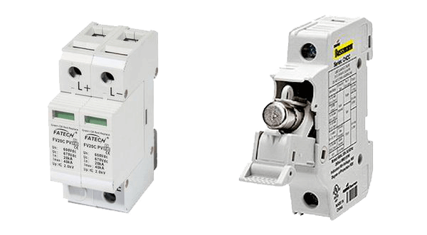
Check all internal surge suppressors and/or fuses when a sign is being serviced. Surge suppressors are installed on all power DIN rails throughout a sign. A faulty surge suppressor will have a red or orange indicator. A good surge suppressor will have a white or green indicator.
If a faulty surge suppressor is found, obtain a replacement by contacting us.
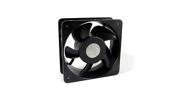
It's good practice to check the fans and ventilation any time the sign is being serviced. Our signs have temperature sensors within the LED sign cabinet that monitor internal cabinet temperature. If the internal temperature reaches 152°F (67°C) the display is turned off, which stops the heat generation by the electronics.
This over-temperature condition may occur if the sign installation has blocked the ventilation, or if an excessive number of fans have failed. Ventilation can also be compromised by obstructions to airflow; for example, from leaves, dirt, rodents, insects or birds. Safely remove these obstructions if observed during sign servicing.
Part Replacement
Below you will find instructions for replacing or servicing individual LED display components. To purchase parts for your LED sign or request them through our warranty service, please contact us.
![]() LED Maintenance Manual
for printable instructions.
LED Maintenance Manual
for printable instructions.
A power supply converts 120V or 220V electrical current to a lower voltage, and provides it to one or more internal components within your LED display. While how you access the power supply depends on the sign model, the instructions for replacing it are the same.
- Disconnect power from the sign and open the LED cabinet of the affected side. Turn off the internal power switch (if equipped).
- Locate the power supply that needs to be replaced.
- Disconnect the 110 volt or 220 volt AC power from the power supply. The wires are marked on the power supply by L (live), N (neutral) and ⏚ (ground). The live wire is black, neutral is white or red, and ground is green.
- Remove the 5 volt DC power wires from the power supply. The wires are marked on the power supply by V+ (positive) and V- (negative). The red wires are positive and black wires are negative.
- Remove the four screws on the right side of the power supply and remove the unit. Install the new power supply by securing it with the four screws on the right side.
- Reconnect all power wires to their appropriate locations on the power supply.
- Turn on the internal power switch (if equipped). Close the sign and restore power.
A sensor may detect ambient light or temperature conditions of the sign. How it is replaced depends on the type and model of sensor. A temperature sensor may also be referred to as a temperature probe, and is only required for signs using PC-installed software.
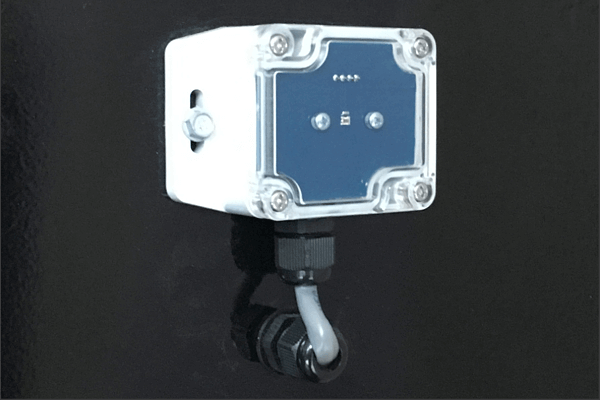
- Disconnect power from the sign and open the LED cabinet of the side with the light sensor. The sensor is typically located on the end of the LED cabinet.
- Follow the cable that exits the bottom of the light sensor until it ends at the sensor hub. Disconnect the cable from the hub and remove any zip ties that secure it.
- Remove the hex head screws that fasten the sensor box to the cabinet.
- Pull the cable out through the black cord grip, loosening it if necessary.
- Attach the new sensor in the same location using the hex head screws, and feed the cable back through the cord grip.
- Plug the end of the cable into the sensor hub.
- Close the sign and restore power.
- Disconnect power from the sign and open the LED cabinet of the side with the temperature sensor. The sensor is typically located at the bottom right corner of the LED cabinet.
- Follow the cable that exits the top of the temperature sensor until it ends. Depending on the model, the cable may end at a sensor hub or at the controller.
- Disconnect the temperature sensor and remove any zip ties that secure it to the back of the LED cabinet.
- Loosen the sensor strain relief by turning counter-clockwise, and remove the sensor from inside the cabinet.
- Install the new sensor into the strain relief. There should be at least one inch of the sensor that sticks out the bottom of the cabinet. Turn the strain relief clockwise to tighten.
- Plug the sensor cord into the sensor hub or controller, depending on model.
- It's recommended to secure the cable by zip tying it to the back of the LED cabinet. This will prevent it from getting hung up on other components when opening and closing the sign.
- Close the sign and restore power.
LED modules are the square or rectangular panels that form your LED display. Most DayStar and VividStar signs use dual maintenance modules. All TekStar and some DayStar signs use rear maintenance modules. When upgrading or changing modules with different power connectors, a non-standard installation may be required.
- Disconnect power from the sign.
- Locate the service points on the front of the LED module to be replaced. If necessary, the service points can also be accessed from the back by opening the LED cabinet.
- Insert a 3mm Allen wrench into the service points, and rotate one quarter turn counter-clockwise.
- Carefully pull out the LED module and disconnect the ribbon cables and power wires.
- Ensure the locator arrows are pointing outward before connecting the replacement module.
- Reconnect the ribbon and power cables. The connections are direction-specific. Do not use force when connecting them.
- Place the new LED module into the sign. Insert the Allen wrench into each service point, and rotate one quarter turn clockwise to secure the module.
- Restore power to the sign.
- Disconnect power from the sign and open the LED cabinet of the affected side. Locate the module to be replaced.
- Disconnect the ribbon cables, making note of their location.
- Remove the power wires using a #2 Phillips screwdriver.
- Remove the screws holding the module to the sign using a #2 Phillips screwdriver.
- Before attaching the replacement module, ensure that the locator pins are correctly positioned and that the module sits flush within the sign. Attach new module with the screws.
- Reconnect the power wires.
- Reconnect all ribbon cables as they were connected to the old module. Do not use force when connecting them.
- Close the sign and restore power.
A controller may also be referred to as a PC controller or IPC. It may be gray or dark blue in color. The controller can be identified as the component with a power button and various USB and video ports.
- Disconnect power from the sign and open the LED cabinet (side A for double-sided signs). Locate the controller within the sign.
- Disconnect all of the cables attached to the controller, making note of their location. This includes a power cable, a video cable (either HDMI or DVI), all USB cables, and an Ethernet cable.
- Remove the four screws holding the controller to the sign with a #2 Phillips screwdriver, and remove the controller.
- Place the new controller in the same location and secure with the Phillips screws.
- Reconnect all of the cables to the controller. The USB cables can be connected to any USB port.
- Close the sign and restore power.
A receive card may also be referred to as a receiver card or logic card. It may be red or green in color. A receive card can be identified as a card connecting to the send card or other receive card with an Ethernet cable. As there may be multiple receive cards per sign side, speak with a technician to identify the card(s) for replacement.
- Disconnect power from the sign and open the LED cabinet of the affected side.
- Locate the receive card within the sign.
- Disconnect the power connector from the card.
- Remove all Ethernet cables and ribbon cables attached to the card. Make note of their location for accurate re-installation.
- Remove the four screws that secure the card with a #2 Phillips head screwdriver.
- Remove the card, being careful not to lose the four white standoffs.
- Replace the card and re-secure using the four screws and standoffs.
- Reattach the power connector, Ethernet cable(s) and ribbon cable(s).
- Close the sign and restore power.
A send card may also be referred to as a sender card or DVI card. It may be red or green in color. The send card can be identified as the card with the video cable (HDMI or DVI) running to the controller.
- Disconnect power from the sign and open the LED cabinet of the affected side.
- Locate the send card within the sign.
- Disconnect the power connector from the card.
- Remove all Ethernet cables attached to the card. Make note of their location for accurate re-installation.
- Remove the four screws that secure the card with a #2 Phillips head screwdriver.
- Remove the card, being careful not to lose the four white standoffs.
- Place the new card in the correct position and re-secure using the four screws and standoffs.
- Reattach the power connector and Ethernet cable(s).
- Close the sign and restore power.
The USB box may also be referred to as a Mencom box. This water-tight box houses the USB port for your sign. The USB box is typically attached to one end of the sign cabinet.
- Disconnect power from the sign and open the LED cabinet of the side with the USB box.
- Remove the USB box from the sign. This component is secured with either four 5/16" hex screws, or four #2 square head screws.
- From inside the LED cabinet, disconnect the USB cable from the controller.
- Tie a string to the USB cable and pull the cable outward until the connector is out of the sign.
- Remove the string and attach it to the cable on the new USB box. If you have a USB lock bracket, thread the cable through the bracket.
- Using the string pull the cable back up into the sign.
- Attach the USB box and bracket to the sign.
- Reconnect the USB cable to the controller.
- If you are using the USB lock bracket, use a padlock with a shackle of at least 5 inches in length.
- Close the sign and restore power.
These instructions are for the TekStar integrated sign face. For instructions on replacing a DayStar sign face, see the instructions on opening a sign cabinet .
- Disconnect power from the sign.
- Using a 5/16 inch nut driver, remove the three screws along the bottom of each side of the sign. Once loose, the panel will swing freely towards you.
- Using a 1/4 inch nut driver, remove the hex head screws from the inside of each bottom corner. This will release the bottom retainer. Take the retainer off and place to the side.
- Slide the old face down and out of the side retainers.
- Slide the new face into side retainers. Continue sliding upward until it meets the top retainer.
- While holding the face in place, attach the bottom retainer with the screws in both corners.
- If you are replacing both faces on a double-sided sign, repeat the process for the other face.
- Restore power to the sign.